
Robotics - Making URDF models
In a previous post I talked about simulating the SCUTTLE robot using ROS and Gazebo. I used Gazebo to simulate the SCUTTLE robot so that I could learn more about ROS without needing to involve a real robot with all the setup and complications that come with that. Additionally when I was designing the bump sensor for SCUTTLE using the simulation allowed me to reduce the feedback time compared to testing the design on a physical robot. This speeds up the design iteration process and allowed me to quickly and verify the design and the code. In the end you always need to do the final testing on a real robot, but by using simulation you can quickly iterate to a solution that will most likely work without major issues.
In order to progress my swerve drive robot I wanted to verify that the control algorithms that I had developed would work for an actual robot. Ideally before spending money on the hardware. So I decided to use Gazebo to run some simulations that would enable me to verify the control algorithm.
The first step in using Gazebo is to create a model of the robot and its surrounding environment. Gazebo natively uses the SDF format to define both the robot and the environment. However if you want ROS nodes to be able to understand the geometry definition of your robot you need to use the URDF format. This is important for instance if you want to make use of the tf2 library to transform between different coordinate frames then your ROS nodes will have to have the geometry of the robot available.
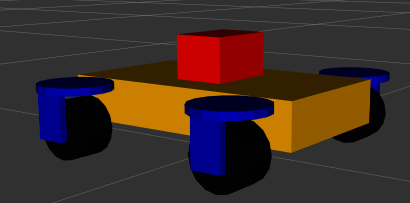
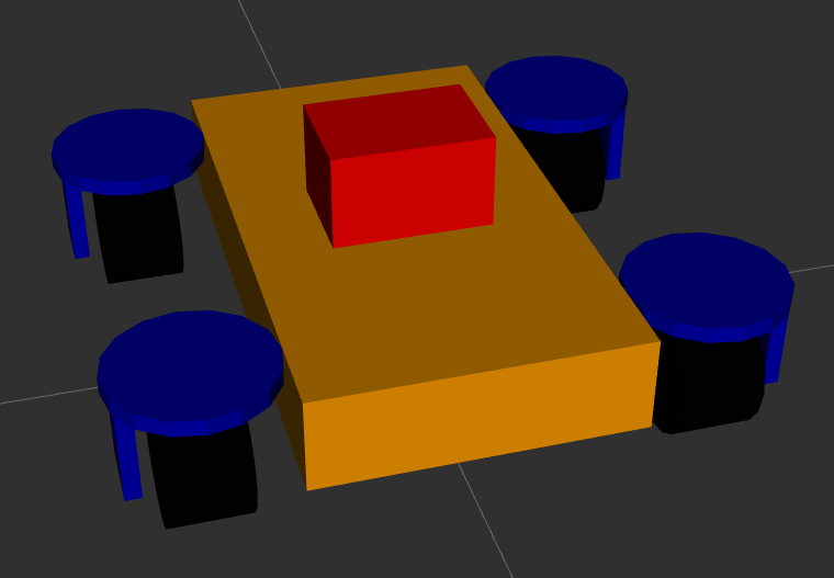
There are different ways to create an URDF model. One way is to draw the robot in a CAD program and then use a plugin to export the model to an URDF file. This is a relatively quick approach, it takes time to create the robot in the CAD program but then the export is very quick. The drawback of this method is that the resulting URDF file is not very clean which makes it harder to edit later on. Additionally the CAD software will use meshes for both the visual geometry and the collision geometry. As discussed below this can lead to issues with the collision detection. Another way is to create the URDF manually. This approach is slower than the CAD export approach, however it results in a much more minimal and clean URDF file. This makes editing the file at a later stage a lot easier. Additionally manually creating the URDF file give you a better understanding of the URDF format and how it works. In the end the model for my swerve drive robot is very simple, consisting of a body, four wheels, the steering and drive controllers and the sensors. So I decided to create the URDF file manually. The images below show the resulting model in RViz. The model consists of the robot body in orange, the four drive modules in blue and black, and the lidar unit in red.
The URDF model describes the different parts of the robot relative to each other. The robot parts consist of the physical parts of the robot, the sensors and the actuators. The physical parts, e.g. the wheels or the body, are described using links. The links are connected to each other using joints. Joints allow the links to move relative to each other. Joints can be fixed, e.g. when two structural parts are statically connected to each other, or they can be movable. If a joint is movable then be one of:
- A revolute joint, which allows the two links to rotate relative to each other around a single axis.
- A continuous joint, which is similar to a revolute joint but allows the joint to rotate continuously without any limits.
- A prismatic joint, which allows the two links to move relative to each other along a single axis.
- A floating joint, which allows the two links to move relative to each other in 6 degrees of freedom.
- A planar joint, which allows the two links to move relative to each other in 3 degrees of freedom in a plane.
In the URDF file each link defines the visual geometry, the collision geometry and the inertial properties for that link. The visual and collision geometry can be defined either by a primitive (box, cylinder or sphere) or a triangle mesh. It is recommended to use simple primitives for the collision geometry since these make the collision calculations faster and more stable. If you use a triangle mesh for the collision geometry then you can get issues with the collision detection. This can lead to the robot moving around when it shouldn't. For instance when the wheel of the robot is modelled as a triangle mesh then the collision calculation between the wheel and the ground may not be numerically stable which leads to undesired movement of the robot. The current version of the SCUTTLE URDF has this problem as is shown in the video below. In a future post I'll describe how to fix this.
Using meshes for the visual geometry is fine as this geometry is only used for the visual representation of the robot. Note that the meshes should be relatively simple as well since Gazebo will have to render the meshes in real time which is expensive if the mesh consists of a large number of vertices and triangles.
I normally start by defining a link that represents the footprint
of the robot on the ground, called base_footprint. This link doesn't define any geometry, it is
only used to define the origin of the robot. When navigation is configured it will be referencing
this footprint link. The next link that is defined is the base_link. This link is generally defined
to be the ‘middle’ of the robot frame and it forms the parent for all the other robot parts.
The next step is to define the rest of the links and joints. For the swerve drive robot I have four drive modules, each consisting of a wheel and a steering motor. The wheel is connected to the steering motor using a continuous joint. The steering motor is connected to the base link using another continuous joint. Because the four modules are all the same I use the xacro format. This allows me to define a single module as a template and then use that template to create the four modules. The benefit of this is that it makes the URDF file easier to edit and a lot smaller and easier to read.
To add sensors you need to add two pieces of information, the information about the sensor body and, if you are using gazebo, the information about the sensors behaviour. The former consist of the visual and collision geometry of the sensor. The latter consists of the sensor plugin that is used to simulate the sensor. For the swerve drive robot I have two sensors, a lidar and an IMU. The lidar is used to provide a point cloud for the different SLAM algorithms which allow the robot to determine where it is and what the environment looks like. The Gazebo configuration is based on the use of a rplidar sensor. The IMU is experimental and currently not used in any of the control algorithms. The Gazebo configuration is based on a generic IMU.
The last part of the URDF file is the definition of the ROS2 control
interface. This interface allows you to control the different joints of the robot using ROS2 topics.
The ROS2 control configuration consists of the general configuration
and the configuration specific to Gazebo.
It should be noted that the Gazebo specific configuration depends on linking to the correct control
plugin for Gazebo. In my case, using ROS2 Humble,
and Gazebo Ignition Fortress, I need to use the
ign_ros2_control-system plugin with the ign_ros2_control::IgnitionROS2ControlPlugin entrypoint.
For other versions of ROS2 and Gazebo you may need to use a different plugin.
When you are using this information to create your URDF model there are a number of issues that you may run into. The main ones I ran in to are:
- ROS2 control documentation is lacking in that it doesn't necessarily exist for the combination of your version of ROS and Gazebo. That means you need to look at the source code to figure out the names of the plugins and which controllers are available. For instance ROS2 control defines a joint trajectory controller. This controller should be able to work with a velocity trajectory, i.e. a trajectory that defines changes in velocity. However the current implementation of the controller doesn't support this. Additionally the Gazebo plugin doesn't support all the controller types that are available in ROS2 control. To find out which controllers actually work in Gazebo you need to search the source code of the Gazebo control plugin.
- In order to run ROS2 control you need to load the controller manager.
This component manages the lifecyle of the controllers. However when running in Gazebo you shouldn't
to load the controller manager as Gazebo loads one for you. If you do load the controller manager
then you will get an error message that the controller manager is already loaded. Also note that in
order to optionally load the controller when using the Python launch files you need to use the
unless
construct, not the Python
if .. thenapproach. The latter doesn't work due to the delayed evaluation of the launch file. - The start up order of the ROS2 control controllers relative to other ROS nodes is important. When
the controllers start they will try to get the joint and link descriptions from the
robot state publisher. This won't be running until after the simulation starts. So you need to delay the start of the controllers until after the robot is loaded in Gazebo and the state publisher node is running. - Unlike with ROS1 if you want your ROS2 nodes to get information from Gazebo, e.g. the simulation
time or the current position or velocity of a joint, then you need to set up a
ROS bridge.
This is because Gazebo no longer connects to the ROS2 messaging system automatically. For my simulation
I bridged the following topics:
/clock- The simulation time. This was bridged unidirectionally from Gazebo to ROS2 into the/clocktopic./cmd_vel- The velocity commands for the robot. This was bridged bidirectionally between Gazebo and ROS2./model/<ROBOT_NAME>/poseand/model/<ROBOT_NAME>/pose_static- The position of the robot in the simulation as seen by the simulation. This was bridged unidirectionally from Gazebo to ROS2 into the/ground_truth_poseand/ground_truth_pose_statictopics./model/<ROBOT_NAME>/tf- The transformation between the different coordinate frames of the robot as seen by the simulation. This was bridged unidirectionally from Gazebo to ROS2 into the/model/<ROBOT_NAME>/tftopic./<LIDAR_NAME>/scanand/<LIDAR_NAME>/scan/points- The point cloud from the lidar sensor. These were bridged unidirectionally from Gazebo to ROS2 into the/scanand/scan/pointstopics./world/<WORLD_NAME>/model/<MODEL_NAME>/link/<IMU_SENSOR_LINK_NAME>/sensor/<IMU_NAME>/imu- The IMU data. This was bridged unidirectionally from Gazebo to ROS2 into the/imutopic.
Finally one issue that applies specifically to ROS2 Humble and Gazebo Ignition has to do with the fact that Gazebo Ignition was renamed back to Gazebo. This means that some of the plugins have been renamed as well. So the information you find on the internet about the correct name of the plugin may be out of date.
Once you have the URDF you need to get Gazebo to load it. This is done in two parts. First you need
to load the robot state publisher and provide it with the robot description (URDF). The code below
provides an example on how to achieve this.
def generate_launch_description():
    is_simulation = LaunchConfiguration("use_sim_time")
    use_fake_hardware = LaunchConfiguration("use_fake_hardware")
    fake_sensor_commands = LaunchConfiguration("fake_sensor_commands")

    robot_description_content = Command(
        [
            PathJoinSubstitution([FindExecutable(name="xacro")]),
            " ",
            PathJoinSubstitution([get_package_share_directory('zinger_description'), "urdf", 'base.xacro']),
            " ",
            "is_simulation:=",
            is_simulation,
             " ",
            "use_fake_hardware:=",
            use_fake_hardware,
            " ",
            "fake_sensor_commands:=",
            fake_sensor_commands,
        ]
    )
    robot_description = {"robot_description": ParameterValue(robot_description_content, value_type=str)}

    # Takes the joint positions from the 'joint_state' topic and updates the position of the robot with tf2.
    robot_state_publisher = Node(
        package='robot_state_publisher',
        executable='robot_state_publisher',
        name='robot_state_publisher',
        output='screen',
        parameters=[
            {'use_sim_time': LaunchConfiguration('use_sim_time')},
            robot_description,
        ],
    )

    ld = LaunchDescription(ARGUMENTS)
    ld.add_action(robot_state_publisher)
    return ld
Then you need to spawn the robot in Gazebo. Assuming you're using Gazebo Ignition then you can use
the ros_ign_gazebo package with the command line as shown below.
    def generate_launch_description():
        spawn_robot = Node(
            package='ros_ign_gazebo',
            executable='create',
            arguments=[
                '-name', LaunchConfiguration('robot_name'),
                '-x', x,
                '-y', y,
                '-z', z,
                '-Y', yaw,
                '-topic', '/robot_description'],
            output='screen')

        ld = LaunchDescription(ARGUMENTS)
        ld.add_action(spawn_robot)

        return ld
Once you have set this all up you should be able to run Gazebo and see your robot in the simulation. At this point you can then control the robot using the ROS2 control interface by sending the appropriate messages. For an example you can look at the test control library for the swerve robot. That should allow you to get the robot moving as shown in the video. In the video two different control commands are given. One controls the motion of the steering actuators and makes the wheels steer from left to right and back again on a timed loop. The other controls the motion of the wheels, driving them forwards and then backwards, also on a timed loop. Obviously this is not a good way to control the robot, but it does allow you to verify that you have correctly configured all the parts of your robot for use in Gazebo.