
Starting robotics - Building a bumper for scuttle. The electronics
The final part of building a bumper for SCUTTLE is to assemble the electronics component which translates the movement of the bumper into signals which can be processed by the bumper software. In order to do this I designed a simple circuit using KiCad and advice from one of the many robotics forums.
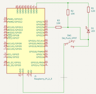
The circuit contains a microswitch as the trigger. The switch is connected to one of the 3.3V output pins on the raspberry PI 4 board on one side and to one of the GPIO pins on the other side. When the switch is depressed the circuit closes and the GPIO pin is driven to 3.3V, which is considered a high signal. In order to ensure that the voltage on the GPIO pin is 0V when the circuit is not closed I added a pull down resistor. On the raspberry PI it is possible to programmatically add a pull down resistor, however because I'm using this as a learning exercise I thought it would be more suitable to include a physical pull down resistor in the circuit.
The next thing I wanted from the circuit was the ability to see if the circuit was closed or not, so that when I'm debugging it is obvious if there is a problem with the power, electronics or software. For this purpose I added a yellow LED to the circuit, which lights up when the circuit is closed. Adding the LED then adds the requirement to protect it from over current in case that the input pin was programmed to be an output pin by mistake. For this purpose I added a resistor next to the input pin.
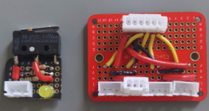
After testing the circuit on the breadboard the next step was to solder two switch boards and a distribution board. Each switch board would have a micro-switch, the LED, the resistors and a JST-XH three pin connector for power, ground and signal wires. The distribution board would have four JST-XH three pin connectors and one JST-XH six pin connector. The four three pin connectors would allow me to have a front bumper and a rear bumper, each having a switch board on the left and the right. I used JST-XH connectors instead of the Dupont connectors because the JST connectors are directional, thereby removing any potential issues with plugging the connector in the wrong way.
Part of this journey involved learning how to solder electronics components. I bought a Weller WE 1010 soldering station for this and future jobs. I managed to do a reasonable job soldering the parts but it is obvious that I still have a lot to learn when it comes to soldering.
The last task was to crimp the connectors and connect the boards. Because the raspberry Pi has a Dupont header I needed to crimp both Dupont connectors and JST-XH connectors. For the Dupont connectors I got an Iwiss SN-025 crimper. It works pretty well for those connectors. However the crimper dies are too wide for the JST-XH connectors. So to crimp the JST-XH connectors I had to get a different crimper with narrower dies. So for this I got an Engineer PAD-11 crimper. While this is not a ratcheting crimper it works really well, at least for the JST-XH connectors.
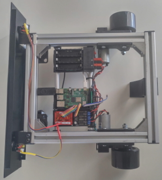
So now that the mechanical setup is done, the software is, mostly, done and the electronics have been soldered and connected my bumper works. Sort of. It turns out that there is a problems with my SCUTTLE that make the bump response only work partially. It seems that there is an issue with the wheel encoders, which causes the software to not know how much one of the wheels has rotated. I will discuss fixing the encoders in another post.