
Starting robotics - Building a bumper for scuttle. The software
In my previous post I talked about creating a bump sensor for my SCUTTLE robot. After creating the mechanical design I started working on the software. There are two parts to the software, translating the state of the micro switches and turning the state changes into movement commands for the robot, i.e. if the robot runs into an obstacle it should stop and reverse its last movement. I decided to create a ROS node for each of these actions, i.e. one node for the movement generation and one to translate the switch states. The reason for creating two nodes instead of putting all the code into one node is that this allows me to run the movement generation code both in a simulation and on the physical robot. So I gain the ability to test more of my code, but I lose a bit of performance because the two nodes communicate using messages which is slower than just using method calls.
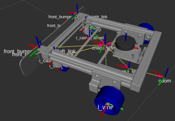
To test the bump sensor code I use Gazebo to simulate how the bump sensor would work. Gazebo has the ability to calculate collisions and create ContactsState messages based on these collision calculations. So I created a third ROS node to translate these Gazebo messages to my own bumper event messages. With that I can test my obstacle response code in Gazebo which provides a more controlled environment than the physical robot does.
The first thing to do is to update the robot definition to include the bumper. This is done by adding the links and joints that make up my bumper to an URDF file. This URDF file is linked to the main model description for SCUTTLE. After that I added the information for the Gazebo bumper sensor. In the URDF file this looks as follows:
    <gazebo reference="front_bumper_plate_left_link">
        <sensor name="front_bumper_left" type="contact">
            <selfCollide>true</selfCollide>
            <alwaysOn>true</alwaysOn>
            <updateRate>15.0</updateRate>
            <material>Gazebo/WhiteGlow</material>
            <contact>
                <collision>base_link_fixed_joint_lump__front_bumper_plate_left_cl_collision_3</collision>
                <topic>bumper_contact</topic>
            </contact>
            <plugin name="gazebo_ros_bumper_controller_front_left" filename="libgazebo_ros_bumper.so">
                <bumperTopicName>scuttle_bumper</bumperTopicName>
                <frameName>front_bumper_plate_left_link</frameName>
            </plugin>
        </sensor>
    </gazebo>
I found that defining a contact sensor for Gazebo requires getting the link ID correct. In order to do so you need to follow these steps:
- The bumper contact information needs to be defined inside a
gazeboelement. Thisgazeboelement should have areferenceattribute that points to the link that is to be used as the bumper surface. - The name for the
collisionelement needs to be found after translation to the SDF format. Normally this is something Gazebo does internally. In this case you'll need to do this manually. If your geometry is defined in an xacro file then you first need to translate this to URDF using therosrun xacro xacro --inorder -o model.urdf model.urdf.xacrocommand. After that you can translate the URDF to SDF with thegz sdf -p scuttle.urdf > scuttle.sdfcommand. Once you have the SDF file you can search for the correct element IDs.
In the above example the collision name, base_link_fixed_joint_lump__front_bumper_plate_left_cl_collision_3,
is the one you need to extract from the SDF file. Note that it can change if you make changes to
your xacro / URDF file, so in that case you will need to extract it again.
Once you have defined the URDF Gazebo will generate contact messages when the bumper hits an object. These contact messages contain information describing where the contact occurred on the geometry mesh, so in theory I could have used this information to determine if the contact would trigger the left limit switch or the right limit switch or both. However that requires a decent amount of calculations which is both work and introduces the potential for errors. So I opted to split the bumper into two parts, one for the left side and one for the right side. If anything contacts anywhere on the left side I consider that a trigger for the left part of the bumper and similar for the right side.
With the URDF work done I started writing the code for the different ROS nodes. First the gazebo translator node. This node subscribes to the ContactsState messages that Gazebo sends when the bumper geometry collides with something. These messages are then translated to a BumperEvent message for further processing.
One interesting observation about the Gazebo contact messages are that they exhibit something similar to switch bounce, in other words it seems that the contact is intermittent even if the bumper plate is in solid contact with the object. I'm guessing that this is caused by the fact that calculating collisions between moving surfaces is difficult. In the end it doesn't matter what causes this behaviour though because we need to deal with it in some sensible way.
Once the bumper event messages have been generated they are processed by the second node. This node subscribes to both odometry events and bumper events. Internally it keeps track of the motion state of SCUTTLE. On reception of a bumper event the node sends a velocity command to stop the robot. Once the robot has stopped it sends commands for it to reverse course far enough that it is no longer contact with the obstacle.
One thing to note is that while the bumper code is working to reverse course after hitting an obstacle, the other parts of ROS, e.g. the navigation stack, are probably still trying to steer the robot in the original direction because those parts don't know about the obstacle. After all it is not on the navigation map. This results in many different velocity commands being send, which could be very confusing for the robot. One design decision was to make the bumper code unaware of other nodes. This was done because allowing the bumper code to supress velocity commands from other nodes would imply that the bumper code is always the most important publisher when it comes to velocity commands. There are cases where this isn't true, e.g. when using the bumpers to park SCUTTLE against a specific object like in the case of a docking station.
To ensure that a consistent set of velocity commands are sent to the motors I used the twist multiplexer node which takes in velocity commands from many nodes and forwards them using a priority-based scheme. In the current implementation the priorities are, from low to high
- Navigation
- Keyboard
- Bumper
- Joypad / Joystick
By using the twist multiplexer mode it is easy for users to change the priority by changing a configuration file instead of having to change the bumper code.
With that the bumper code is able to make SCUTTLE respond to objects it bumps into. The next step in the process of adding bump sensors to SCUTTLE is to assemble the electronic components so that the movement of the bumper can be registered and reported to the software components.
Finally a addition to the software that needs to be made is the ability to add the obstacles in the navigation map so that SCUTTLE can navigate around the newly discovered obstacles.