
Starting robotics - Fixing the wheel encoders
While testing the bumper for SCUTTLE I noticed that when reversing SCUTTLE would start a turn instead of driving straight backwards due to one motor turning faster than the other motor. There are a number of reasons this could be happening, for instance the driver code isn't properly commanding the motors, or the encoders are returning incorrect data, etc..
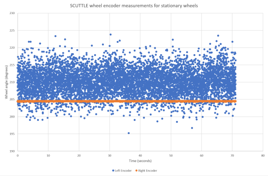
The first thing I did for my investigation was to make sure my encoders provide sensible data. The non-ROS SCUTTLE code contains a useful Python script to measure the current value of the wheel encoders in a loop. I ran this code for a few minutes while the wheels were stationary. In theory the results of this measurement should be two consistent values, one for the left encoder and one for the right encoder. As you can see in the graph it turns out that the angle measurement provided by the left encoder was very noisy.
While a noisy encoder shouldn't by itself cause the incorrect reversing pattern, it will make it more difficult to find the actual cause of the problem. So before I address the bumper reversing behaviour I needed to fix the encoder noise. The two main reasons for noisy encoder data that I could think of were:
- The encoder is broken in some way. SCUTTLE uses the AS5048A position sensor which is relatively robust, but can be broken if you send the I2c commands on the wrong pins. Which could happen if you say ... put the connector on the wrong way when assembling your SCUTTLE ...
- The distance between the encoder and the magnet on the motor shaft isn't correct. The specifications for the encoder state that the distance between the chip and the magnet on the motor shaft should be between 0.5mm and 2.5mm, assuming a magnet of the recommended size and strength is used.
I tried measuring the distance between the encoder and the magnet, but that isn't easy. There is no way to get a measuring tool near that space so I had to resort to indirect measurements. I measured the left and right brackets. They were about 0.5mm difference in size. That doesn't seem much but it would be enough to push the encoder out too far from the magnet.
One solution would be to slightly sand the taller bracket so that both brackets are the size height. In doing that I would have to be very careful to ensure that I sand the bracket flat, i.e. with no change in angle in the face. A second solution is to remove the encoders from their brackets and swap the brackets over.
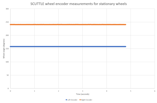
As the latter is relatively easy to do that is the first solution I tried. I took the encoders of their brackets and attached them to the other bracket. These brackets were put back on SCUTTLE and the test script was executed once again. And this time both encoders gave me consistent results. I was expecting the other encoder to go bad due to distance, but apparently both encoders are with in the distance specification with this new configuration.
With the encoder issue fixed I can get back to diagnosing the issue with the bumper reverse action. My current suspicion is that the issue is caused by the fact that the the current SCUTTLE driver code is written as an open loop. This means that there is no feedback to the motor control software that indicates how fast the wheels are actually turning in response to a given motor input. And because even motors of the same type are all slightly different, they all react differently to the same motor input. In my case at low speeds one of my motors responds earlier than the other motor. In the end this means that at low speeds the bumper code thinks scuttle is driving backwards in a straight line while it is actually driving around in circles.