
Starting robotics - Building a bumper for scuttle. The overview
In order to allow my SCUTTLE robot to drive around autonomously it needs some sensors so that it can perceive its surroundings. One of the ways in which this is normally achieved is by adding a LIDAR unit. Unfortunately I don't have one of those, and LIDAR units are relatively expensive in New Zealand. Additionally I figured I'd learn more about robot sensors if I set up some simple sensors for my SCUTTLE robot before getting a LIDAR.
So I decided to start with the simplest kind of sensor, the bump sensor. This type of sensor consists of one or more limit switches and a bumper surface, i.e. some kind of plate that bumps into things. This plate is held in place by springs thereby giving it the ability to move while also returning to its original position. When the robot bumps into an object with the plate, the springs are compressed and the plate hits the limit switches. These switches then signal the robot that it has hit something. At that point the robot can stop its motion and back away from the obstacle. As the robot backs away the springs push the bumper plate away from the limit switches. The change in switch state then signals to the robot that it is no longer in contact with the obstacle and can thus continue on its journey.
Overall this doesn't sound very complicated so it should be pretty quick and easy to build the bump sensor ...
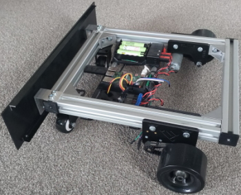
Several weeks down the line I nearly finished my bump sensors
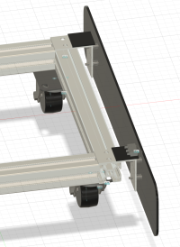
The first part of my build was the design of the physical parts that I need to attach to SCUTTLE. I build the bumper with simple parts because I don't have access to a workshop or a 3D printer. So the bumper is a UHMWPE plate reinforced by some 90 degree aluminium extrusions. This prevents the plate from flexing when it contacts an obstacle. The plate is attached to two angle brackets, one on the left side and one on the right side. It is attached using four M3 bolts wrapped with springs, 2 bolts for each side. The idea behind using 2 bolts per side is that this should provide some rotational stability while keeping the construction simple. Finally the angle brackets is attached to the scuttle frame with two T slot nuts.
I found that the springs that keep the plate in the extended position have to be quite soft, otherwise SCUTTLE won't be able to compress the springs when it hits something at low speed. The first set of springs I got from Amazon were too stiff. For the second set of springs I got some ballpoint pen springs of Aliexpress which are much less stiff.
This first version of the bumper mechanics works relatively well but for the next version there are some things I want to change
- The bolts have full thread on them which sometimes causes the bolts to get hung up on the tread. I had some issues finding partially threaded bolts with the right length and diameter.
- The current design allows left to right tilt which is good, but also top to bottom tilt. The latter is not so good as it potentially allows SCUTTLE to hit an obstacle without noticing. A better design would allow left to right rotation of the bumper but little to no top to bottom rotation. This allows the left and right limit switches to be triggered individually when SCUTTLE hits an obstacle on the left or right side respectively while ensuring that the limit switches are always triggered if the bumper hits something, even if the obstacle is low to the ground.
- The current bumper shape is a flat plate, it would be better if the bumper plate was curved. If the curved bumper is given the right radius it would allow SCUTTLE to rotate in place after hitting an obstacle without getting stuck. Obviously creating a curved bumper will increase construction effort.
The mechanical design of the bumper is only one part of the task. In order for SCUTTLE to be able to respond to hitting an object I need to have have software that can respond to signals from the limit switches and the appropriate electronics that transfers the limit switch state to the raspberry pi. The electronics and the software that I created for this bumper will be described in separate posts.